
Updates are made periodically as I find more money to blow on things I don't really need, follow the Github Repo to be notified of changes or Instagram to follow along in real time.
Wiring#
All crimpers are not created equal, and cheaping out on wiring tooling was a mistake. Amazon special crimps and crimp tools were used, and it is almost certain they will cause issues in the future.
This HP Academy article goes into detail on better tools.
Where possible, Deutsch DT connectors were used to standardize hardware and build modular components. There is a small upfront cost in tooling but the better connector is worth the price.
Most of the existing wiring was re-used for simplicities sake, however TXL is a good budget friendly middle ground for when new wiring was needed. 16 and 20 gauge TXL wire was used, with spools available from Remington Industries. 100' spools of 10 color wire are a good value with free shipping available.
Main Power#
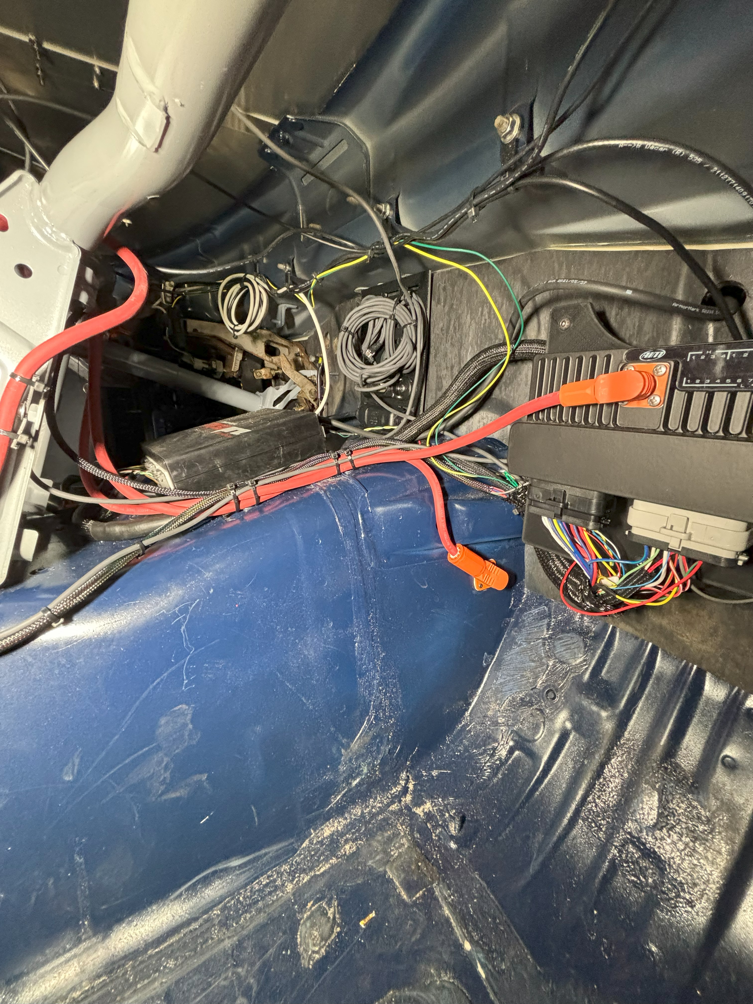
The main Battery Positive (B+) connection is 4AWG and runs through the interior to the center console main disconnect switch. The output of the disconnect splits to two points: A SURLOK connector on the transmission tunnel and the PDM input feed. The SURLOK documentation shows the stud is M8...but neglects to clarify it's M8x1.00 fine thread. Additionally the SLPRBTPSO distribution lug will require hydraulic crimpers to properly terminate. Trying to use a pair of manual large-gauge cable crimps will end with broken crimpers and a disgusting looking crimp that can thankfully be hidden inside of the connector body.
![]()
Starting and Charging#
The starter and alternator primary studs are connected to the transmission tunnel distribution block, which connects them back to B+. The alternator voltage reference wire is also connected to this distribution block. It would be more ideal to run the reference wire directly to the B+ terminal, but the voltage drop along the 4AWG B+ cable should be minimal.
Engine Wiring Harness#
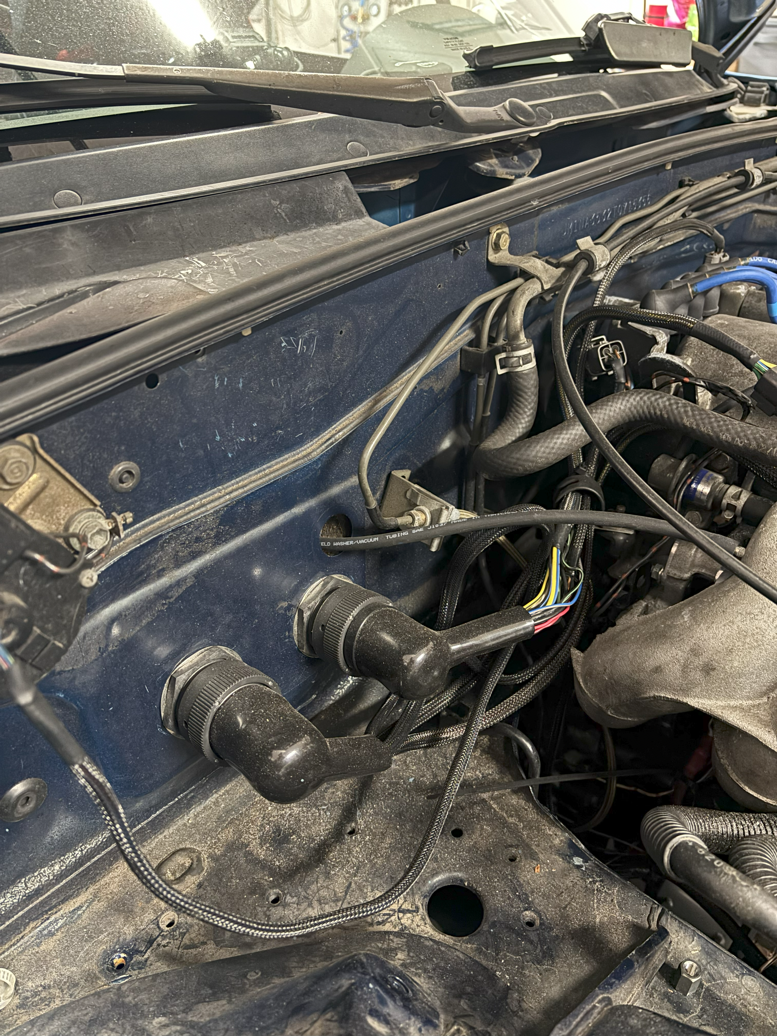
The engine wiring harness was designed to be quick-disconnect by way of two circular connectors. Amphenol circular connectors were chosen for cost reasons compared to their motorsport-equivalent. Instead of running the front-of-engine sensors around the side, they are instead routed through the valley between the intake and fuel rail to allow for a more condensed setup. One connector is dedicated for ECU and sensors, while the other has a few larger pins for high power demand items and is mostly dedicated for power into the engine bay.
PDM#
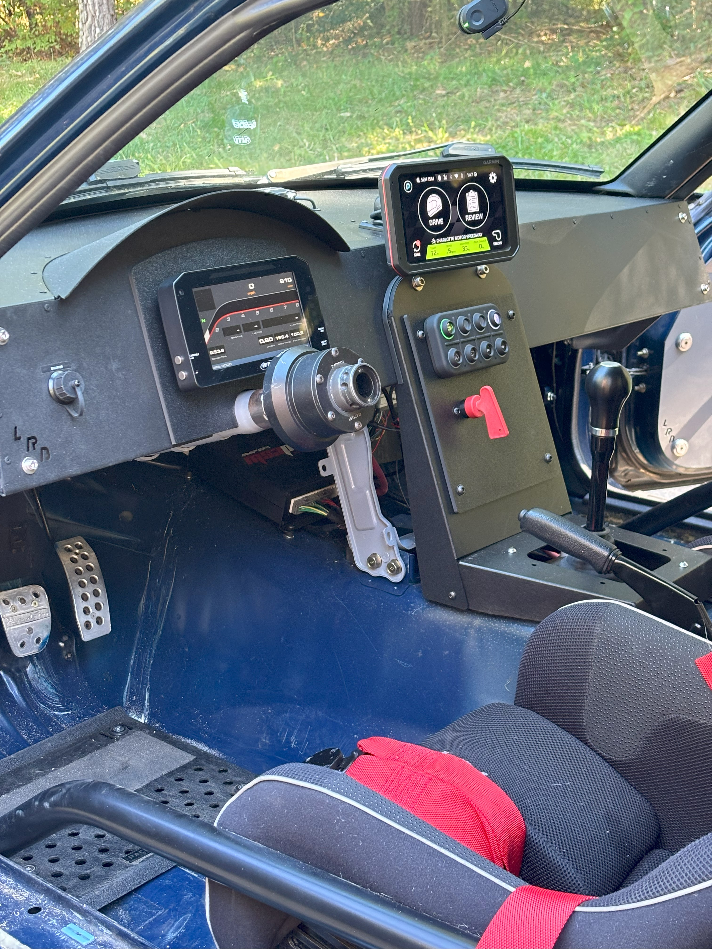
An AIM PDM32 was chosen because it bundles data logging, GPS, digital dash, and an IMU sensor into a single package at an expensive-but-not-outrageous price point. Being a tiny Miata, the 6" dash was most appropriate.
The AIM PDM32 has two 35 pin connectors, one gray (G) and one black (B).
For reasons unknown, the PDM ignored logic that directly referenced input channels. Instead, a status variable had to be created which was controlled by the given channel, and then this variable referenced in other logic blocks.
Connectors#
The PDM has two 35 pin AMP connectors for input/output channels. The red wedgelock on the front of the connector must be unlocked, but not removed when inserting pins. To depin, twist and pull the wire.
This video gives a good demonstration on pinning/depinning the connector.
Powering up#
The AIM PDM32 requires +12v on pin G23 and GND on pin G13/G14 to turn on. A small wire is run directly from the disconnect switch in the center console in order to provide +12v to G23.
Alternator Field#
The Miata has a fairly standard 3-wire alternator with Sense, Field, and +B connections. The PDM supplies the +12v required to the Field (Exciter) connection in order to power the field winding and generate electricity. A 220Ω resistor is connected inline to the Field connection since the original warning light has been removed.
Calculated Gear#
The PDM was configured to display calculated gear number based on GPS speed and gearing.
Parameter |
Value |
|---|---|
| Wheel Circumference | 1803mm (245/45/15 RS4) |
| Axle (Diff) Ratio | 4.1 |
| Gear 1 | 3.136 |
| Gear 2 | 1.888 |
| Gear 3 | 1.33 |
| Gear 4 | 1 |
| Gear 5 | 0.814 |
Reference
Fuel Pump#
The Megasquirt ECU commands fuel pump on via pulling pin 1U to ground. This is fed into pin G26 (Channel Input 1) on the PDM, and switches on B8 (Mid Power 7) to engage the fuel pump.
Fuel Level#
The fuel level sender requires a pull up resistor to create a voltage divider. On a 1996 NA8 Miata, the sender measures 3Ω at full and 95Ω at empty. Using a 1kΩ resistor as a pull up, the following min/max sensor voltages can be calculated:
-
Minimum Output Voltage (Full Tank)
-
Maximum Output Voltage (Empty Tank)
This is close, but real world testing revealed the following measurements:
Fuel (gal) |
mV |
|---|---|
| 0 | 505 |
| 0.5 | 505 |
| 1 | 505 |
| 1.5 | 505 |
| 2 | 385 |
| 2.5 | 315 |
| 3 | 297 |
| 3.5 | 278 |
| 4 | 247 |
| 4.5 | 224 |
| 5 | 207 |
| 5.5 | 180 |
| 6 | 164 |
| 6.5 | 164 |
| 7 | 141 |
| 7.5 | 120 |
| 8 | 107 |
| 8.5 | 97 |
| 9 | 87 |
| 9.5 | 78 |
| 10 | 68 |
| 10.5 | 58 |
| 11 | 53 |
| 11.5 | 43 |
| 12 | 24 |
| 12.5 | 24 |
| 13 | 24 |
| 13.25 | 24 |
The tank was emptied and then refilled 0.5 gallons at a time recording the measurement of the fuel level sensor in the PDM. There is a dead zone at the top and bottom of the range, however setting a "Low Fuel" warning at 2 gallons is adequate.
Reference
Wiper Control#
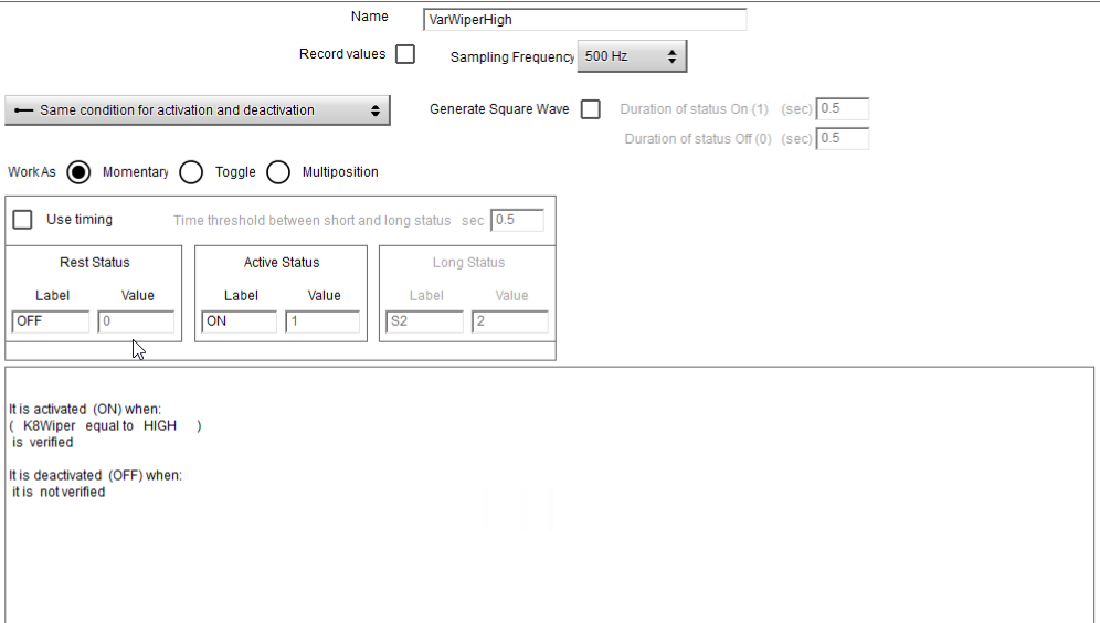
By far the most convoluted thing to set up has been the Wipers. They are controlled via CAN keypad mapped to a multistable digital input with channel values of 0-2 for Off, Low, High. The NA Miata has a typical 5 wire wiper setup, with high/low/B+/park/ground. As the wipers wipe, an internal switch is activated when the wipers are in the "park" position which is fed back into the PDM. In the stock setup this park signal is fed back via relay to the low speed motor winding, so the motor self-powers even after the wiper switch is turned off. The problem is that the PDM cannot react fast enough to the park signal and so it shuts the wipers down when they are 1/4 of the way up the windscreen. To work around this, an additional timed wipe is executed after the wiper button is disengaged
Physical connections:
Wire |
PDM Pin |
Function |
|---|---|---|
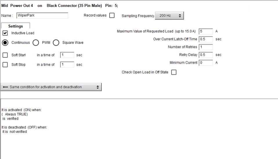
| BLU | B5 MP4 | WIPER PARK +12v |
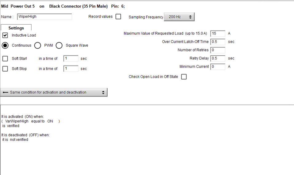
| BLU/RED | B6 MP5 | WIPER HIGH |
| BLUE/WHT | G1 HB1 | WIPER LOW |
| BLUE/YEL | G30 IN5 | WIPER PARK SW |
Logical connections:
- Park
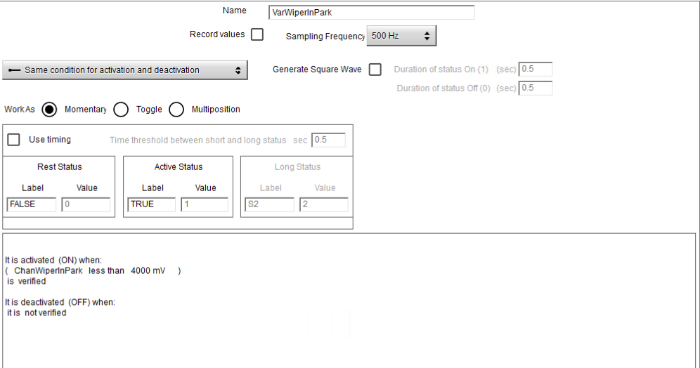
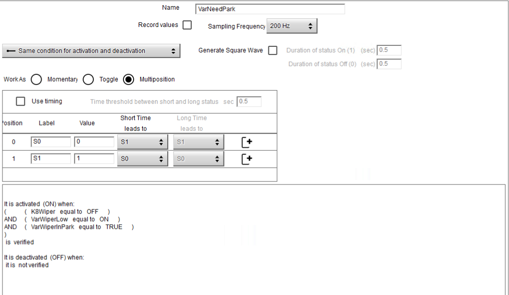
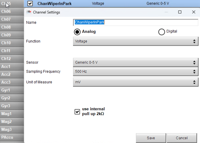
- VarWiperInPark is True when wiper is in the park position. VarNeedPark is a multiposition switch that acts as a counter when the wipers are turned off mid-cycle. It will increment to S1 the first time it parks after being commanded off and this kicks off a timer in WiperLowHB. WiperPark output supplies power to the park switch, which is then read back by the PDM. ChanWiperInPark is an analog input at max sampling frequency as a digital input does not sample fast enough to read the park switch.
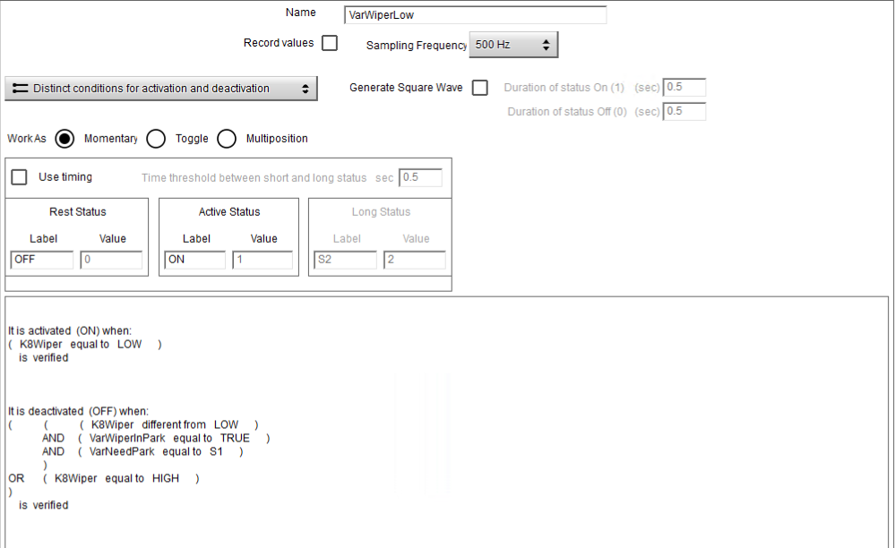
- Low Speed
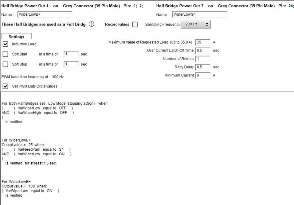
- Controls low speed power output. When wipers are commanded off mid-cycle they will do one additional wipe and then start a 1.5 second timer. When this timer expires, the low speed PWM changes from 100% to 25% slowing the wipers down enough they will gracefully park instead of bouncing. A HB is used here to try and brake the motor when it shuts off, even though it doesn't really work because of the PDM reaction lag. Only one side of the HB is wired, which supplies power to the low speed winding.
- High Speed
- Controls high speed power output.
Reference:
- AIM PDM Wipers
- Iain Hall Wiper Motor Wiring
- Wiper Control with an AIM PDM32
- AIM PDM Users Facebook Group
- Facebook Post (mirrored below)
Facebook Group Post
Wiper control, recap of what worked.
1) An analog input (rather than digital) at a high frequency (maybe 200Hz) gives faster PARK feedback to the PDM. Digital inputs are limited to 20Hz. You'll need a pull-up resistor. I got bad data (switch chatter) with 2200 ohms. Going to 220 ohms fixed that.
2) Assuming you have a high and low speed feeds (and don't have to reverse the motors yourself), you should use a full-bridge to power the low or high speed input. You don't have to actually wire the ground, but you want the logic to brake the motor when in park. RS3 cannot brake in half-bridge mode.
3) Not sure if I still need this, but I used PWM to slow the motor during parking. An issue is that the frequency in full-bridge mode is limited. To get around this, I use 1000Hz 60% PWM during parking and put the full-bridge on the high speed signal. Take care in your programming to avoid simultaneously powering and braking.
4) I use a multi-state status variable to track PARKING NEEDED. It's turned on when either high or low motors are on and turned off when they are both off and the park signal is true. UPDATE: I added a "active after" time of 0.05 seconds to the analog PARK input, which seemed to reduce the problem with switch chatter prematurely stopping the wipers mid-stroke.
Setup:
WiperButton = OFF/INT/LOW/HIGHWiper Int Osc = square wave 1s / 5sUnloadedRun = Run and WiperButton = INTWiper Low Status = UnloadedRun = RUN AND (WiperButton = LOW OR WiperIntOsc = ON OR (WiperButton = OFF and WasherStatus = ON) ) Wiper Hi Status = UnloadedRun = RUN and WiperButton = HIGHWasherStatus = UnloadedRun = RUN and WasherButton = ONWiper Needs Park = ON: Wiper Low Status = ON or Wiper High Status = ON OFF: WiperPark (voltage) > 4vWiper Low (output) = PWM, 1000Hz 100%: Wiper Low Status = ON 60%: Wiper Needs Park = TRY AND Unloaded Run = Run AND Wiper Low Status = OFF and Wiper High Status = OFFWiper High (full bridge) = Both Low (stopping) Wiper Low Status = OFF ANDWiper High Status = OFF AND Wiper Need Park = OFF High: Wiper Hi Status = ON
Again, I'm not sure the PWM is needed, but this is what I'm using right now.
Use a 220 ohm pull up on the analog input between 5v and the input. 200Hz.That means I have a Status Variable labeled Wiper Int Osc which is defied to be a square wave with 1 second on and 5 seconds off. The next = is a typo which I just fixed. Unloaded Run is a status variable which is defined to be Run is TRUE AND keypad wiper button called WiperButton is a multi-step button currently equal to INT. The 4 steps are OFF, INT, LOW, and HI
Start Stop#
A K8 keypad is used to control start/stop functions. All engine power outputs are controlled by a VarEnginePower variable, which is true when either engine RPM is greater than 375 or the K8 Start/Stop button status is LONG. This triggers the starter and once engine RPM is above 375 the VarEnginePower variable is latched true.
To stop the engine, a short press of the K8 Start/Stop button will set VarEnginePower variable to false for 5 seconds, killing ignition power and allowing enough time for the engine to stop running.
ECU#
Mounting#
The ECU is mounted above the trans tunnel via vibration insulators threaded into jack nuts.
Reference
Tuning#
Autotune was enough for getting a decent VE table. Additional tuning to the AE and Idle tables was required.
https://www.youtube.com/@TurbineResearch
Base Timing#
CAN Setup#
The ECU is connected to both the PDM and Wideband controller via CAN. Despite AEM having some proprietary AEMnet elements, no special configuration was needed on either the ECU or PDM. The ECU and PDM provide the required 120Ω resistance termination at each end of the network.
Reference
Some considerations from miataturbo.net:
You have an MS3, an AEM X-Series gauge and you want to feed the wideband signal to the MS3 through the CAN Bus, but you also have other devices on the CAN Bus and you are worried about compatibility. Let's make a a few remarks.
- The CAN Bus can have BOTH 11bit and 29bit messages running through it at the same time. This is perfectly fine and many new cars do this.
- The MS3 uses both 11bit and 29bit CAN.
- 11bit CAN is used for 1-way communication from the MS3 to other devices ("CAN Broadcasting") where the MS3 broadcasts messages and other devices on the bus receive them. It can also be used as "CAN Receiving", where the MS3 also picks up messages broadcasted from other devices.
- 29bit CAN is used by the MS3 for 2-way communication. It's a custom request-respone protocol (although there are 1-way commands on this protocol as well).
- Each CAN message has an ID, also called an address. On the 11bit CAN, this signifies who sent the message or what it contains. There is no way to interpret this; You have to know for example, that the message with ID: 0x100 is sent by the ECU, and it contains the RPM signal, the TPS, the CLT and the IAT.
- On the custom MS3 29bit protocol, things are different. Because 29 bits is a lot of space, you can put the sender address, the receiver address, the command type (ie request data from ECU, send data to ECU, perform a Burn command, etc), the location of the data to request/store, etc. So when you see an MS3 protocol 29bit ID, you know exactly what it is.
The problem here is that the AEM X-Series uses 29bit CAN. The default ID of each message is 0x180. Translated to MS3 CAN, this ID implies:
* This is a message from the MS3 (CAN ID: 0)
* This message is to be received from the device that has a CAN ID of 3.
* The command type is "MSG_CMD", this tells the target device to store the data attached to this message.
* The table to store this message's data on the target device is 0.
* The offset with the table to store this message's data on the target device is 0.
What does this mean? If you DON'T have a device on the CAN Bus that has ID: 3, it is perfectly safe to install the AEM X-Gauge on your bus. It might even be safe to install it even if you have a device on the Bus with an ID: 3, if that device doesn't actually implement the MSG_CMD message type (it will just receive it and ignore it) OR if the device doesn't store data on the table 0, offset 0. How do you know what ID your devices are using? It will be either be in the documentation of your device or the settings of your device. Most MS-compatible devices have configurable CAN IDs. If you still don't know, ask the manufacturer.
Wideband#
The LSU 4.9 has a trim resistor built into the sensor-side connector body, do not attempt to cut this connector off and replace with a DTM connector, it will cost $100 for a new sensor or the controller must be setup for free-air calibration.
This conversion was done due to relocating the Lambda sensor connector to the transmission tunnel and a flanged bulkhead style connector was desired.
Chassis#
Steering#
Power steering was deleted and pinion shaft welded. The 96-97 Miatas use a different power steering rack than earlier NA models, and a hydraulic press is required to push a seal out of the housing.
MotoIQ goes into this process in detail in this blog post.
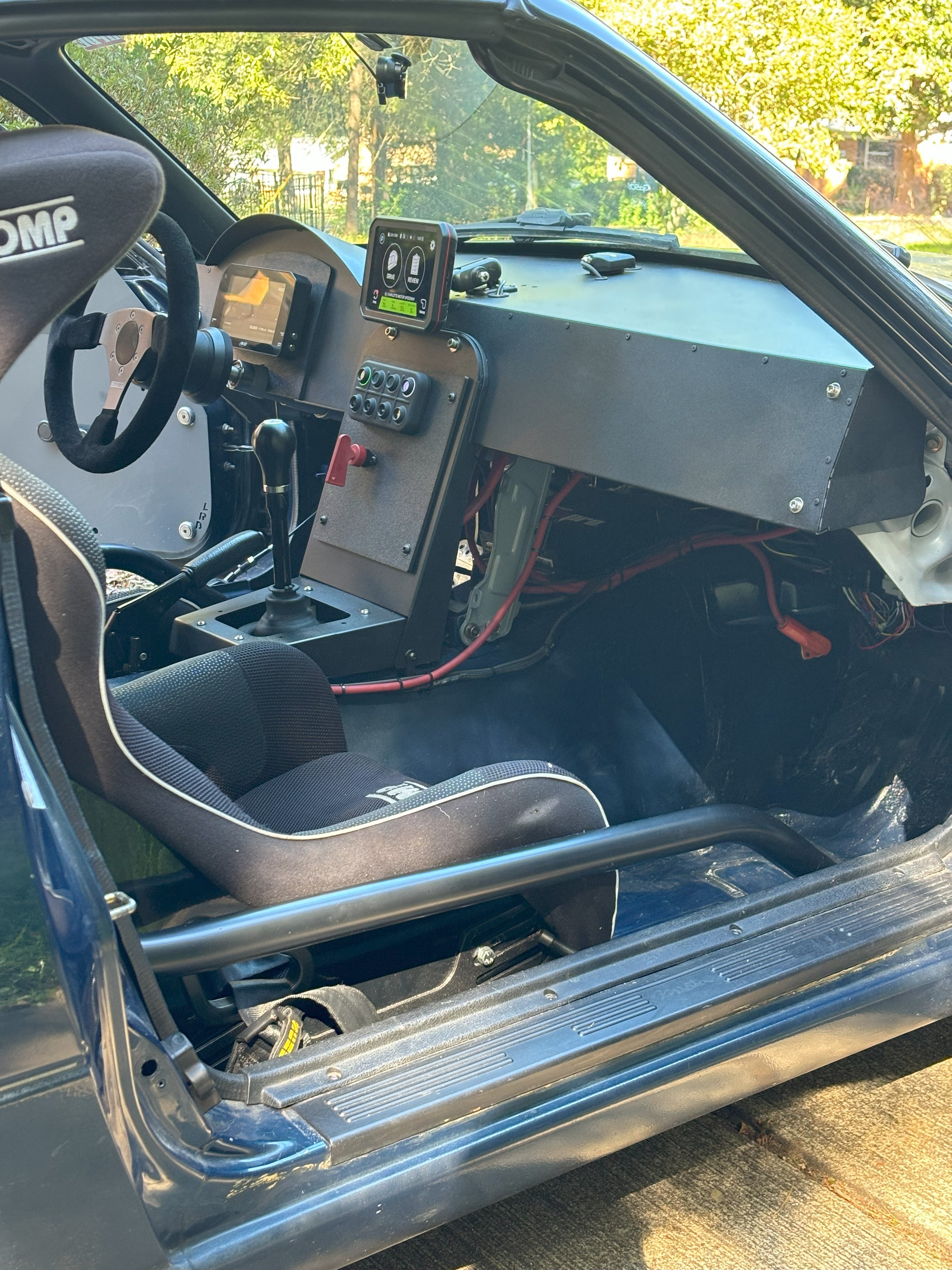
Interior#
Dashboard#
The dash is a custom LRB Speed NA Miata Aluminum Dashboard painted Krylon Textured Black. LRB shows this is only compatible with NA6 ('89-'93) cars, but I had no issues installed it in my NA8 (1996) car.
The PDM and ECU USB outputs were run to a USB hub which is connected to a panel mount USB connector, this allows for quick connection without having to dig around for wires under the dash. I do not have stalk connectors so designed and printed a trim piece that fits behind the PDM dash to cover the stalk switch cutouts.
Exterior#
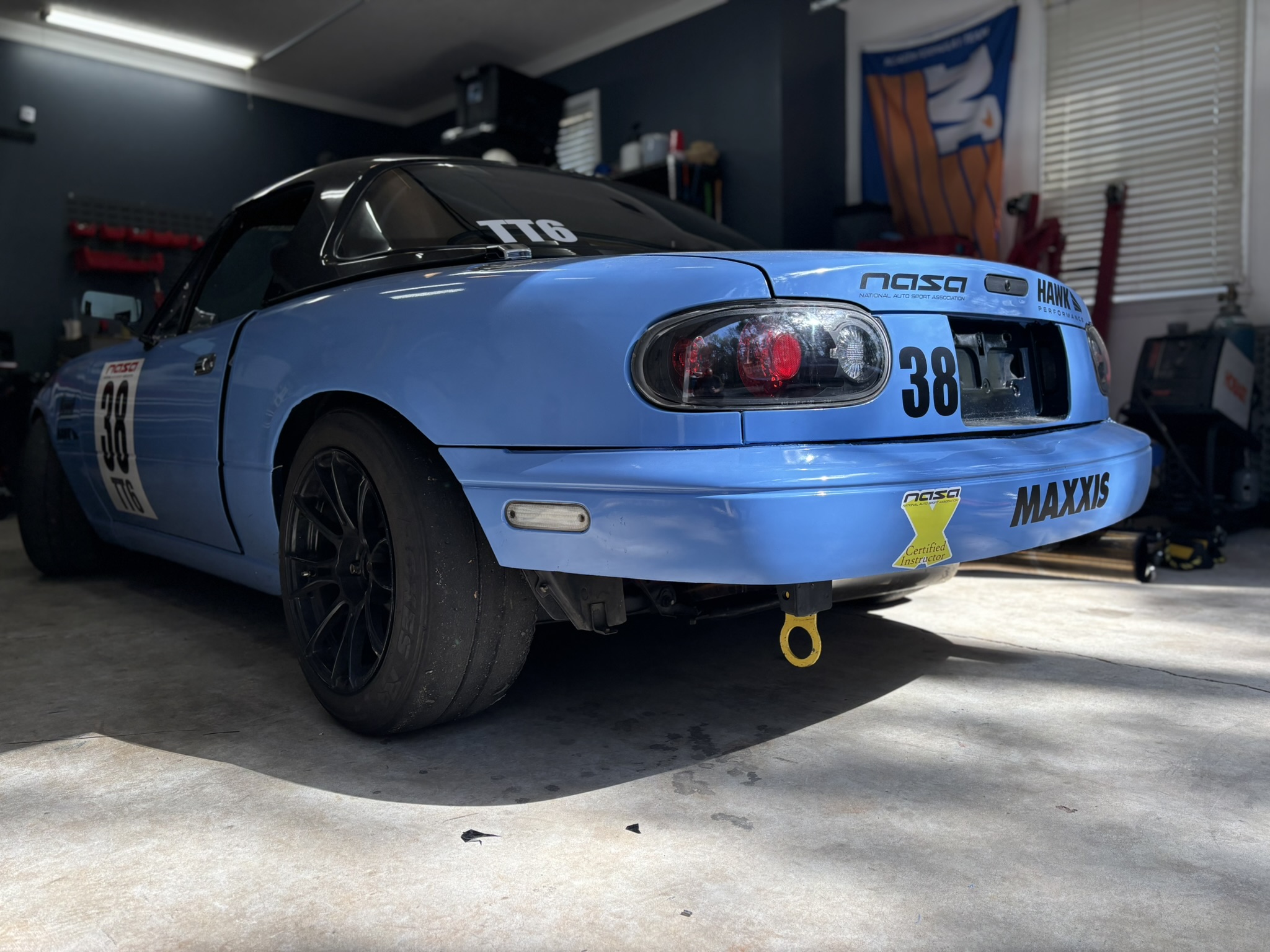
Wrap#
The car is wrapped with Avery Dennison SW900 Gloss Smoky Blue Vinyl Wrap | SW900-612-O. A 5x40 roll was sufficient with a decent amount left over.
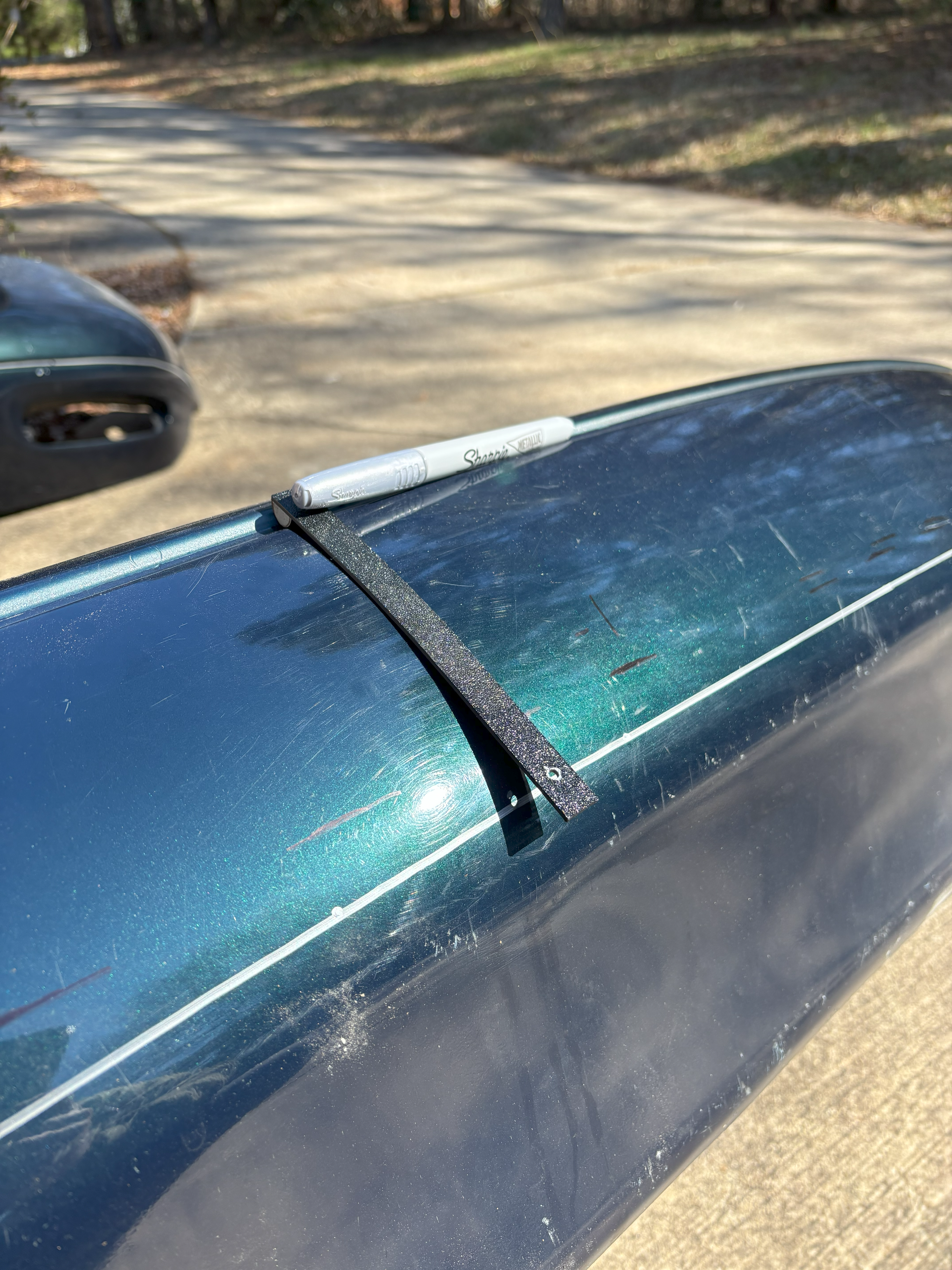
Rear Bumper#
Bumper is cut 5" down from the body line. Removes a lot of plastic while still covering the crash structure and being NASA TT6 legal. This does remove half of the bump support and it ended up a little floppy. Future efforts will be made to inject expanding foam between the yellow bumper support and outer bumper shell to increase support and rigidity. I created a 3d printed jig to mark the cut line around the bumper.
Parts Reference#
Wiring#
Part Number |
Description |
|---|---|
| SLPRBTPSO | B+ Distribution Lug |
| SLPPB25BSO | B+ Cabin PDM Feed |
| HDP24-24-21SE | Engine bay power bulkhead |
| HDP26-24-21PE | Engine bay power plug |
| HDP24-24-31SE | Engine bay sensor bulkhead |
| HDP26-24-31PE | Engine bay sensor plug |
Sensors#
Part Number |
Description |
|---|---|
| Bosch 17212 | LSU 4.9 02 sensor (short wire harness) |